Vacuum chamber is designed taking into account the following assumptions:
- It must host the cage of HV electrodes (called HV cage) and extraction prism inside the vacuum in between the magnet poles.
- In order to minimize impact on impedance it should provide smooth transition between central part hosting the HV cage and the round, standard LHC beam pipe.
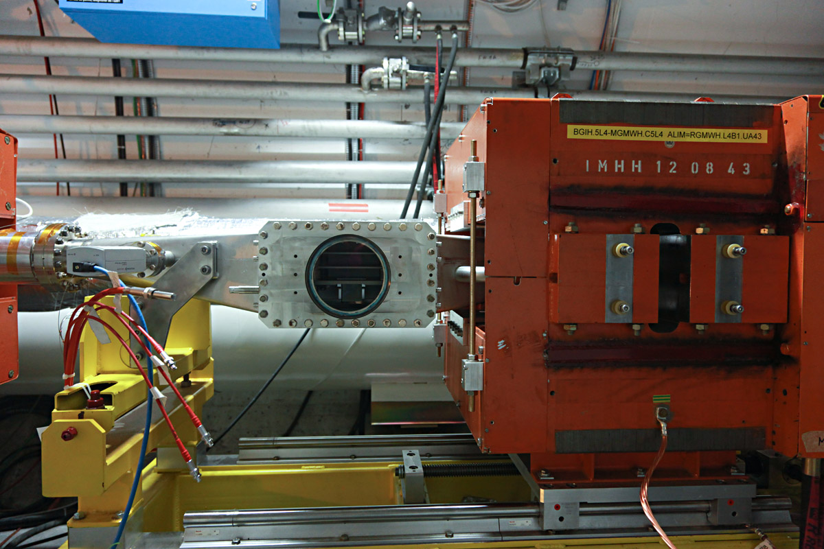
The detector (HV cage, prism) is attached to the flange which contains viewport for transmitting the light to the outside optical system and camera. Photo below shows (if visible) the flange attached to the vacuum chamber as installed in the machine (LHC) with magnet displaced for intervention.
The next photo shows flange in the lab, after cleaning.
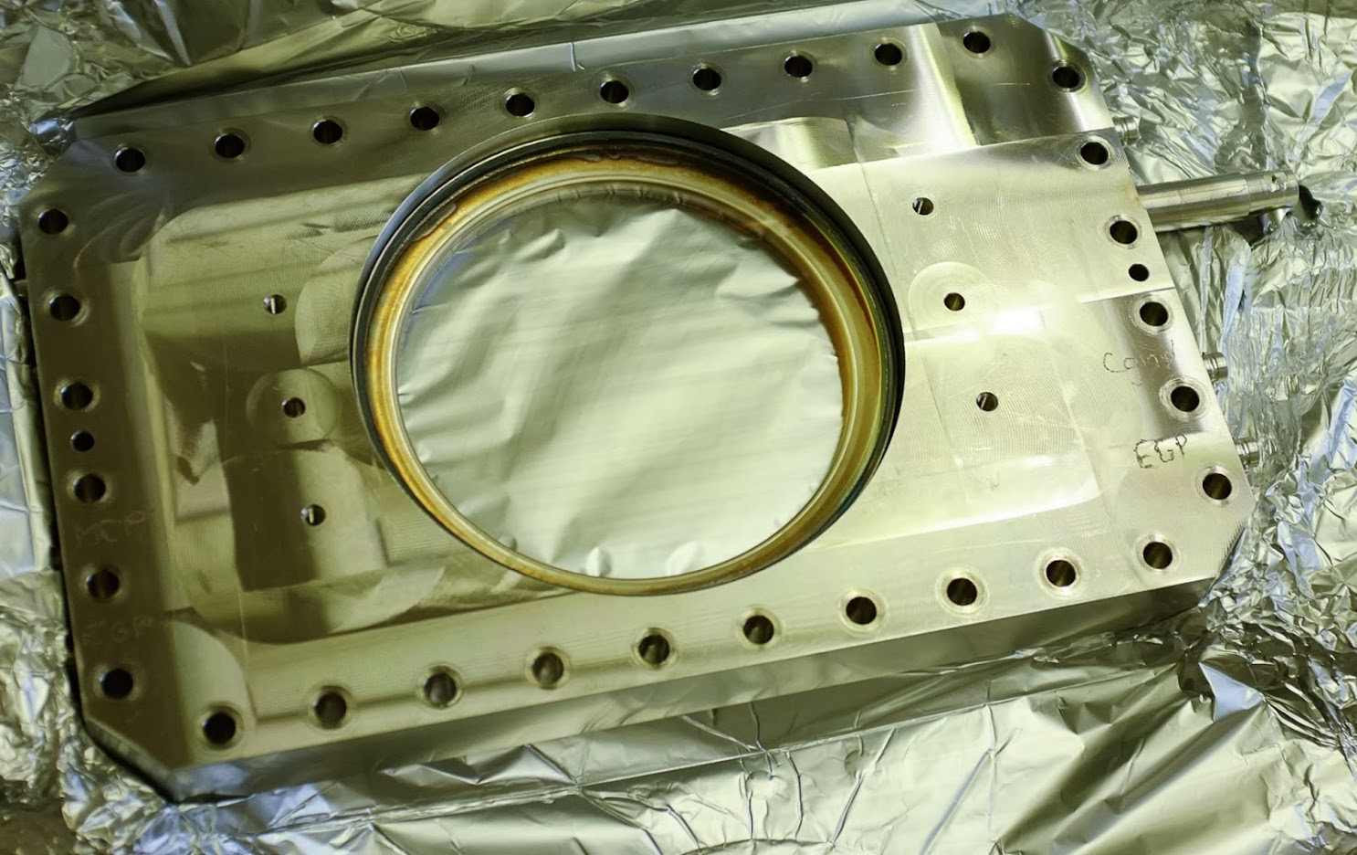
The connection between flange and the vacuum chamber is sealed using Helicoflex metallic seals. Proper istallation of these seals was a subject of study in 2014 (G. Schneider, M. Hamani et others) after a failure to close the detectors in 2012 (detectors were closed but the leak level was just at the limit to be accepted). The outcome of this study was:
- The roughness of the surfaces up to now were not good enough (recommended roughness is about 0.4 um), so special polishing of both: vacuum chamber and the flange is needed.
- HN type seal was more leak-tight then HNV-type one.
- Leak-tightness of HNV-type seal was improved is the spacer thickness increased leaving only 0.6 mm of compression zone (before it was 0.9 mm).
Roughness measurements are described in https://edms.cern.ch/document/1349089/1 (EDMS-1349089).
The HV connectors are installed on the flange. There are 8 connectors, although only 6 of them are used. Seven connectors are normal HV connectors, the 8th one is a special 15 kV connector, rarely found (the same is used for kicker magnets, ref. Mike Barnes).
This special connectors are difficult to find, expensive and obsolete. In the last order Teledyne Reynolds Ltd they were called #167-4534-RG213.